Welcome to the Briggs and Stratton Single Cylinder OHV Repair Manual, a comprehensive guide for maintaining and repairing single-cylinder overhead valve engines. This manual provides detailed instructions, diagrams, and specifications to help technicians and DIY enthusiasts service their engines effectively. Covering disassembly, inspection, servicing, and reassembly, it ensures optimal performance and longevity of your engine. Available as a downloadable PDF, it offers convenient access to expert-level guidance.
Purpose and Scope of the Manual
This manual is designed to assist engine technicians and DIY enthusiasts in maintaining and repairing Briggs & Stratton single-cylinder OHV engines. It provides detailed instructions for disassembly, inspection, servicing, and reassembly, ensuring optimal engine performance. The scope covers various engine models, including Intek, Powerbuilt, and horizontal/vertical configurations, excluding Vanguard engines. The guide includes specifications, torque values, and troubleshooting tips, making it an essential resource for both professionals and hobbyists. By following the manual, users can address common issues, extend engine lifespan, and perform repairs confidently. Its comprehensive coverage ensures all aspects of engine maintenance are addressed thoroughly.
Target Audience and Prerequisites
This manual is primarily intended for small engine technicians, service professionals, and experienced DIY enthusiasts. It assumes a basic understanding of mechanical systems and engine repair principles. Users should possess fundamental tools and safety knowledge. While designed for professionals, it is also accessible to homeowners seeking to maintain or repair their Briggs & Stratton single-cylinder OHV engines. Prior experience with engine disassembly and reassembly is beneficial but not required. The manual serves as a detailed guide for anyone aiming to service or repair these engines effectively, ensuring safe and successful outcomes.
Understanding the Briggs and Stratton Single Cylinder OHV Engine
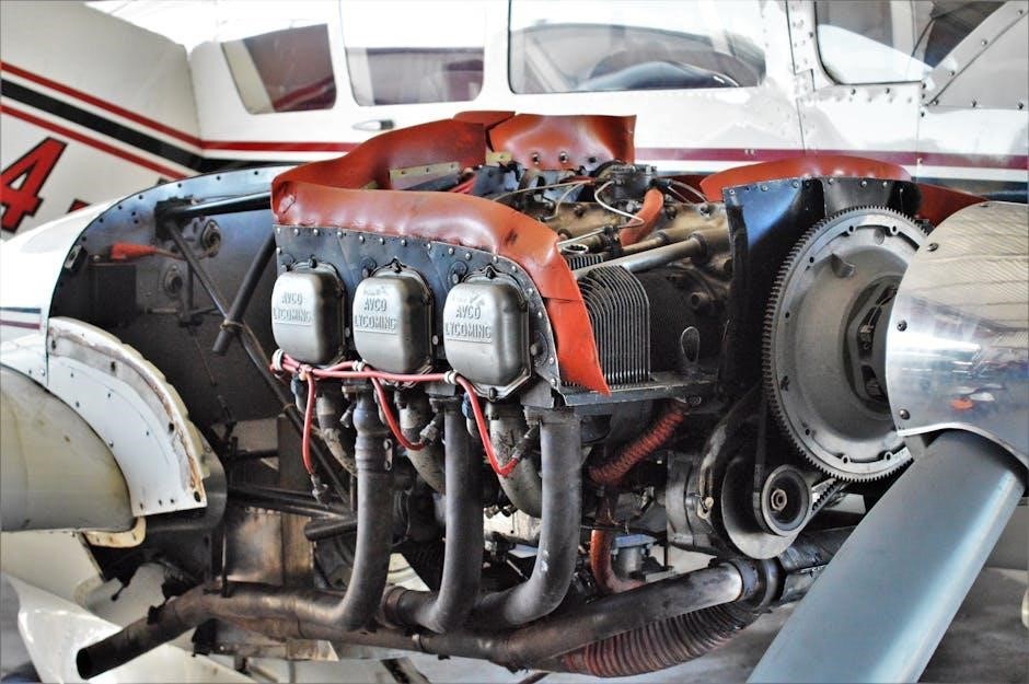
The Briggs & Stratton Single Cylinder OHV engine is a compact, air-cooled power unit designed for reliability and efficiency. Its overhead valve design enhances performance and simplifies maintenance, making it ideal for small equipment like lawn mowers and generators. Built with durable materials, these engines are known for their longevity and ease of service, catering to both residential and commercial applications.
Key Components and Terminology
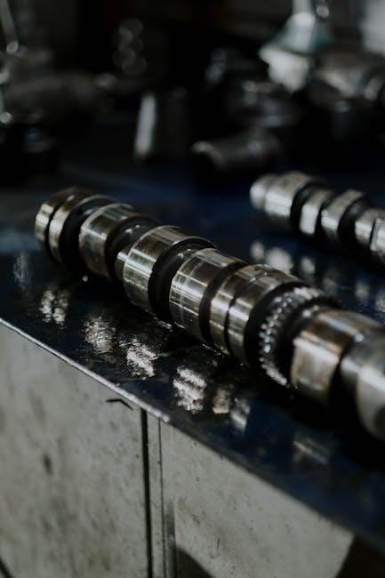
The Briggs & Stratton Single Cylinder OHV engine comprises essential components such as the cylinder head, piston, crankshaft, and camshaft. The overhead valve (OHV) design features valves located in the cylinder head, operated by a rocker arm and pushrod. The air filter, carburetor, and ignition system are critical for fuel delivery and combustion. Key terms include compression ratio, spark plug gap, and torque specifications. Understanding these components and terms is vital for effective servicing and repair, ensuring proper engine function and longevity.
Engine Model Identification and Specifications
Briggs & Stratton Single Cylinder OHV engines are identified by their model numbers, typically located on the engine’s ID tag. Models such as the Intek and Powerbuilt series are covered in this manual. Specifications include horsepower, displacement, and cylinder configuration. The manual details torque values, bolt sizes, and critical measurements for precise repairs. Engine series like 270962, 273521, and 276781 are referenced, ensuring compatibility with various applications. Proper identification ensures accurate servicing, as specifications vary between models. Always consult the manual for exact details to match your engine’s unique requirements.
Disassembly and Inspection Procedures
Disassembly involves removing components like the cylinder head and valve train. Inspect parts for wear or damage, ensuring proper evaluation before servicing or replacement.
Step-by-Step Engine Disassembly Process
The disassembly process begins with disconnecting the spark plug wire and draining the fuel. Remove the air filter and any external components. Next, take off the cylinder head, valve train, and piston assembly. Carefully document each step and label parts for easy reassembly. Remove the crankshaft and connecting rod, ensuring all bearings and seals are inspected. Use specialized tools for components like the flywheel or ignition system. Refer to torque specifications in the manual for proper bolt removal. Keep track of all hardware and store them securely. This methodical approach ensures a smooth and organized disassembly process.
Inspecting Engine Components for Wear or Damage
Inspect all engine components for wear, damage, or corrosion. Examine the cylinder bore for scoring or excessive wear, and measure its diameter to check for taper or out-of-round conditions. Inspect the piston for scoring, cracks, or excessive ring groove wear. Check the piston rings for gaps, wear, or breakage. Visually inspect the valves, valve seats, and guides for pitting, wear, or cracking. Use a micrometer to measure valve stem diameter and clearance. Check the crankshaft for scoring, wear, or bent journals; Measure bearing surfaces and look for excessive play or damage. Replace any components that exceed specified wear limits or show signs of failure.

Servicing and Repairing Engine Subassemblies
Service and repair engine subassemblies, including the cylinder head, valve train, piston, connecting rod, and crankshaft. Clean, inspect, and replace worn or damaged components as needed. Use specialized tools and follow torque specifications to ensure proper reassembly and engine performance. This step ensures reliability and longevity of the engine.
Cylinder Head and Valve Train Service
Service the cylinder head and valve train by first removing the cylinder head and inspecting for wear or damage. Clean the head and check the valve face and seat for proper alignment. Resurface or replace the head if necessary. Inspect the valves, springs, and retainers, replacing any worn or damaged components. Use specialized tools to compress springs and remove valve keepers. Reassemble the valve train, ensuring correct clearance and torque specifications. Apply new gaskets and sealants during reinstallation. Proper servicing ensures optimal engine performance, fuel efficiency, and reduces the risk of future damage. Always follow manufacturer guidelines for precise measurements and torque values.
Piston, Connecting Rod, and Crankshaft Maintenance
Inspect the piston for scoring or excessive wear. Remove the snap ring and piston pin, then slide off the piston and connecting rod assembly. Measure the crankshaft for wear using a micrometer. Replace the main bearings if worn. Clean all components thoroughly. Reassemble the connecting rod and piston, ensuring proper alignment. Install a new piston pin circlip. Lubricate moving parts before reassembly. Check the crankshaft end play and replace the seal if necessary. Proper maintenance ensures smooth engine operation and prevents premature wear. Always refer to torque specifications for bolt tightening to avoid damage. Regular servicing extends the engine’s lifespan and performance.
Reassembly and Testing
Reassembly involves carefully following torque specifications for bolts and connections. Perform a leak test and check for proper engine performance. Validate all systems before operation.
Reassembly Process and Torque Specifications
The reassembly process requires precise attention to detail to ensure proper engine function. Begin by reassembling the cylinder head, ensuring the gasket is correctly seated. Tighten all bolts in a star pattern to the specified torque. Next, reinstall the valvetrain components, aligning the pushrods and rocker arms accurately. The crankshaft and connecting rod should be reattached with care, ensuring proper alignment. Refer to the torque specifications chart for each bolt and nut, using a torque wrench to avoid over-tightening. Finally, reconnect the ignition and fuel systems, and perform a leak test. Use the provided diagrams to verify correct assembly and torque values for optimal performance and longevity.
Post-Repair Engine Testing and Validation
After completing the repair, thoroughly test the engine to ensure proper functionality. Start by checking for oil leaks and verifying the ignition system is operational. Perform a slow-speed test to ensure smooth idling and consistent RPM; Gradually increase the throttle to assess performance under load. Monitor for unusual noises, vibrations, or drops in power. Validate cooling system efficiency and ensure all electrical connections are secure. Refer to the manual for specific test procedures and performance benchmarks. Record findings and address any issues before returning the engine to service. Proper validation ensures reliability, safety, and optimal performance of the repaired engine.
Troubleshooting Common Issues
Identify common issues like poor performance or oil leaks using step-by-step diagnostic procedures. Refer to the manual for detailed troubleshooting guides and repair solutions.
Diagnosing Engine Performance Problems
Diagnosing engine performance issues begins with identifying symptoms like rough running, low power, or failure to start. The manual provides detailed procedures to check ignition systems, fuel flow, and compression. Use tools like compression testers to identify internal issues. Consult the manual for specific diagnostic steps tailored to single-cylinder OHV engines. Pay attention to common problems such as faulty spark plugs, clogged air filters, or improper carburetor adjustments. Follow the troubleshooting charts to isolate the root cause. Refer to torque specifications and service intervals to ensure repairs are done correctly. This section helps users systematically identify and resolve performance-related issues efficiently.
Addressing Oil Leaks and Cooling System Issues
Oil leaks and cooling system problems are common issues addressed in the manual. Inspect gaskets, seals, and drain plugs for signs of wear or damage. Replace faulty components using specified torque values. For cooling systems, ensure proper airflow around the engine by cleaning debris from shrouds and fins. Check for blockages in cooling passages and address them promptly. Refer to the manual for detailed steps on replacing gaskets or seals and servicing cooling-related components. Proper maintenance of these systems ensures optimal engine performance and prevents overheating or oil-related damage. Always follow the manual’s guidelines for accurate repairs.
Safety Precautions and Best Practices
Always wear protective gear, including gloves and eyewear, when working with engines. Ensure proper ventilation and avoid over-tightening components. Follow torque specifications and use approved tools to prevent damage or injury. Keep loose clothing and long hair tied back. Disconnect the spark plug wire before starting repairs. Never smoke or use open flames near flammable materials. Refer to the manual for specific safety guidelines tailored to your engine model and repair procedures.
General Safety Guidelines for Engine Repair
Always wear protective gear, including gloves, safety glasses, and a face mask, when working with engine components. Ensure proper ventilation to avoid inhaling harmful fumes or debris. Disconnect the spark plug wire before starting repairs to prevent accidental engine start-up. Tie back loose clothing and long hair to avoid entanglement with moving parts. Use approved tools and follow torque specifications to prevent damage or injury. Avoid smoking or using open flames near flammable materials. Keep children and unauthorized personnel away from the workspace. Follow all safety warnings in the manual to ensure a safe and successful repair process.
Environmental Considerations and Waste Disposal
Properly dispose of all waste materials, including used oil, filters, and damaged parts, to prevent environmental contamination. Use environmentally friendly cleaning agents and avoid draining fluids into storm drains or waterways. Recycle metal and plastic components whenever possible. Comply with local regulations for hazardous waste disposal. Always refer to the manual for specific guidelines on handling and disposing of engine-related materials. Protect the environment by ensuring all repairs are conducted responsibly, minimizing waste and preventing pollution. Adhere to eco-friendly practices throughout the repair process to maintain sustainability and environmental safety.
Additional Resources and References
Access the downloadable PDF manual for detailed instructions and diagrams. Visit Small Engine Warehouse Australia or authorized Briggs & Stratton dealers for updated resources and technical support.
Recommended Tools and Equipment
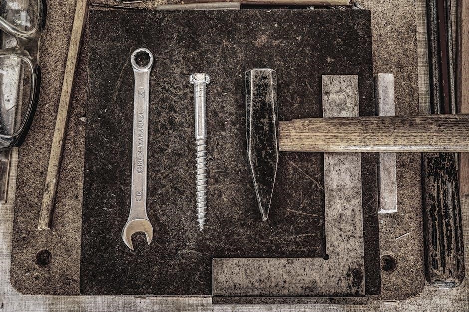
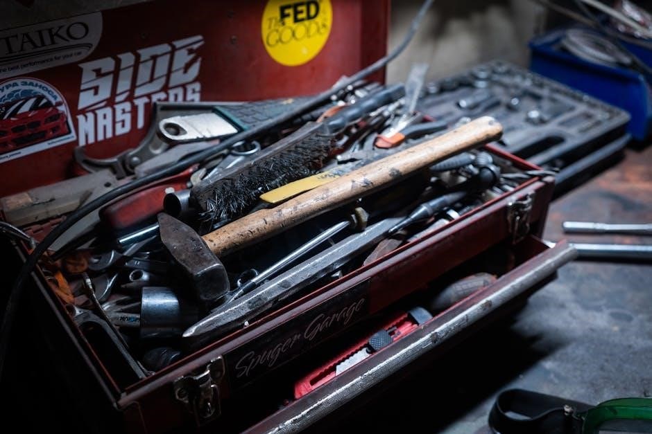
To effectively repair and maintain your Briggs & Stratton Single Cylinder OHV engine, use tools like wrenches, screwdrivers, and pliers. A torque wrench ensures accurate bolt tightening, while a compression gauge aids in diagnosing issues; Specialized tools, such as a piston ring compressor, may be needed for complex tasks. Utilize software like Adobe Reader or SumatraPDF to access the PDF manual. Safety gear, including gloves and goggles, is essential for protection during repairs. Having these tools and equipment on hand will help you follow the manual’s instructions efficiently and safely;
Accessing Updated Manuals and Technical Support
To ensure you have the latest information, download the updated Briggs & Stratton Single Cylinder OHV Repair Manual PDF from authorized sources. Visit the official Briggs & Stratton website or trusted distributors like Small Engine Warehouse Australia for the most recent versions. A download link is typically provided post-purchase for instant access. Use compatible PDF readers like Adobe Reader or SumatraPDF for optimal viewing. For technical support, contact Briggs & Stratton directly or reach out to authorized service centers for troubleshooting and repair guidance. Regularly check for updates to stay informed about new procedures, specifications, and tools, ensuring your repairs are up-to-date and accurate.